Introduction to FEA
Introduction to stress analysis using solid modelling by computer. The techinique that a computer uses to solve complex shapes is called Finite Element Analysis (FEA)
Lecture Notes: ![]() empty.pdf
empty.pdf ![]() empty.one
empty.one
Lecture Video: ![]() Intro to FEA using Inventor
Intro to FEA using Inventor
Why do we need FEA?Standard formulas can only solve standard shapes. FEA can be used to solve complex shapes that cannot be solved with a single formula. In the Stresses subject, we were able to calculate stresses in tension fairly easily, but as soon as bending stresses were involved, things got complicated real quick. You may have also noticed that our torsion formulas were great for circular shafts and pipes, but we never looked at any torsion questions using square pipes or angle sections.
Restrictions included things like;
|
Stress Formulas for Simple Situations (click for large size) |
What is FEA?
FEA stands for Finite Element Analysis.
FEA divides complex geometry into a network of elements, where each element is a simple (solvable) shape. The algorithm then solves each element, calculating stress and elongation using the simple formulas, then moves on to the adjacent elements.
s = F / A e = e / L E = s / e
Actually, it is not really that simple.
The solution is a bit like a truss, except it will be an indetermate truss which is way over-constrained.
So when the first element stretches, it moves the adjacent ones. This creates stress in them also. When they are moved by another element they apply new loads back to the first one. In the end, all these elements must find a position where the forces all balance. This wiill take an infinite amount of time to get it perfectly accurate. So FEA is an approximation, where the user sets the level of accuracy (like 1% or 5% for example). The computer gets a good workout since there are millions of calculations going on. Reducing the size of the elements will dramatically increase processing time.
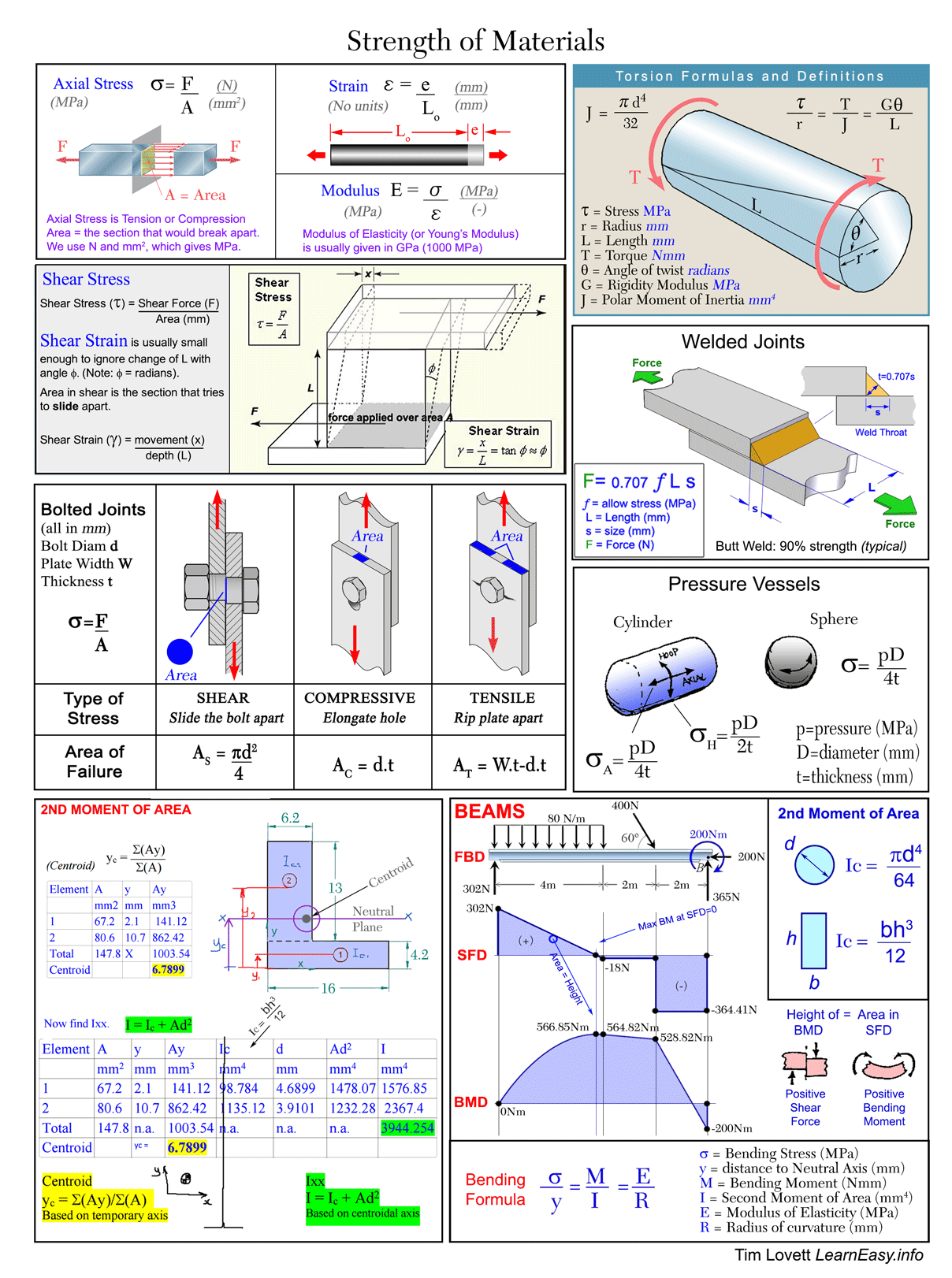
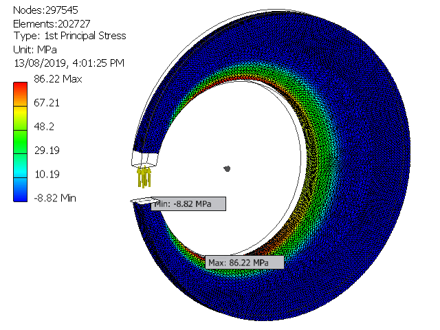
FEA of a "C" FrameIn this example, the lower jaw is fixed and force is applied to the upper jaw - trying to push them apart. The stress is compressive near the jaws, but as the frame begins to take on a curve, these compressive forces start to become bending forces (bending moments). The highest bending moment occurs at the widest point (hence the design), and the maximum stress is 123.2 MPa (Van Mises Stress) There is no "formula" for such a shape, especially if we plan to drill holes to make it lighter! Instead, it is solved by FEA where the complex shape is split into elements. There are 25783 elements in this model. The more elements that are used, the more accurate the result (but the processing dramatically slows)
|
 |
Solution by elements (dividing the whole object into simple elements) has several advantages:
- Almost any geometry can be analysed
- Special material properties can be modelled (e.g. wood or carbon fibre - anisotropic properties)
- Can dig out every possible bit of data (e.g. shear stresses in every 3D plane, deflections in every direction etc)
- Picks up stress concentration effects. (Increased stresss in sharp corners etc)
- Automatically solve a wide varity of problems
What about disadvantages?
- You can get silly numbers. Then you have to work out what went wrong. If you don't realize the numbers are out - then you shouldn't be pretending to do FEA then should you? Always check them with an approximate hand calculation!
- Since it is an approximation, you need to double-check for convergence (when it becomes less sensitive to element size)
- Some loading and constraint situation might be difficult to apply realistically. this depends on how sophisticated the FEA program is. The Inventor FEA is relatively basic, but is quite capable when working within the elastic range of a material.
What can FEA do?
Most things can be solved (or effectively approximated) using FEA, but there are some problems that require more advanced FEA applications.
The basic FEA program solves the stiffness rules;
s = F / A e = e / L E = s / e
These will solve a material only up to the elastic limit.
The big advantage of FEA is that any shape can be analysed.

An excavator arm redesigned for optimal strength (minimum weight) using FEA. This could not be calculated very accurately using formulas, and would be very laborious even to attempt an approximate solution.
Plastic Behaviour
If any plastic deformation is encountered, a small increase in load will dramatically increase the deformation (i.e. Stiffness is reduced after the yield point).
One advancement is to provide anaylsis of plastic behaviour. This will allow the simulation of a car crashing into a barrier for example, where the steel goes beyond the elastic limit.

Wikipedia: Visualization of how a car deforms in an asymmetrical crash using finite element analysis
But there are many more.
What can solve what?1. There is a limited range of simple problems that can be solved using direct formulae (which is what we used in Stresses for instance). 2. By adding Calculus, we are able to increase complexity to include mathematically defined loads and shapes. But this is still quite limited. 3. FEA dramatically increases the range of problems that can be solved, where any shape can be analysed - an engineers dream come true. |
 |
Beyond basic elasticity, FEA can also be extended to include;
- plastic behaviour (beyond the yield point),
- anisotropic materials (where strength is different according to direction, like wood or composites),
- other measurements (e.g. such as temperature variations, shrinkage in a casting)
- dynamic effects (inertia, fluid flow)
- visco-elasticity (the effect of shear velocity in increasing the fluid stiffness - viscosity, in fluids)
- conduction (magnetic, electric, thermal)
Thinking about it:
Imagine calculating stresses on a bicycle.
Match the following bike components to the method of analysis.
| Component | Basic formulae |
Advanced Analysis |
Elastic FEA |
Advanced FEA |
| Spoke | ||||
| Brake cable | ||||
| Frame assembly | ||||
| Crank arm | ||||
| Tyre | ||||
| Wheel assembly |
A quick look at stresses
The Von Mises stress predicts when yield will occur in an isotropic and ductile material (e.g. metal). In a design, the Von Mises stress must stay under the material's tensile yield stress UTS. Problems: There is no such thing as negative Von Mises stress, so you can't tell the difference between tension and compression. |
 |
The 1st principal stress helps you understand the maximum tensile stress induced in the part due to the loading conditions. Here, the tensile stress (86.22 MPa) is very close to the Von-Mises condition (86.06 MPa). This occurs whenever the highest stress condition is pure tension - which it is here. Tensile stress is very much concentrated on the inside surface, with very low tension everywhere else. This is not an efficient design. Note that there is a small negative stress shown.
Double-click in the Browser Bar to set to 1st Principal Stress
|
 |
The 3rd principal stress relates to the maximum compressive stress induced in the part - due to the loading conditions. Here, the compressive stress is coloured in reverse! The highest compressive stress is blue, and the lowest is red. Compressive stress is given as negative values. The maximum compressive stress is -80.94 MPa which occurs on the outside surface.
|
 |
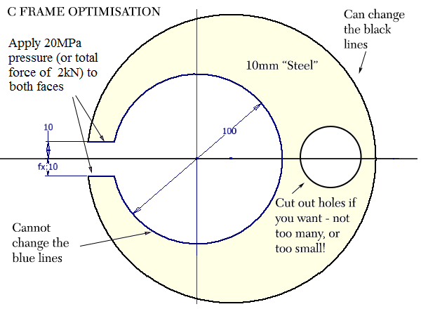
Displacement is how far the object deforms. Note that the deformation shown is usually exaggerated by at least 10 times (or more). This allows the user to visualize the distortion for very stiff materials like steel, where distortion is often too small to notice visually. Maximum displacement in this case is 0.5832 mm. Displacement could be in ANY direction - not just X or Y.
|
 |
Safety factor is based on the material's properties. A high safety fatcor means a safe product. Here, the safety factor does get quite low - into an orange colour, where the minimum is shown as 2.41 Min. We can check this using the maximum stress values; First principle stress = 86 MPa Von Mises stress = 86 MPa (we would use this if it was higher than the maximum tensile, but they are both the same when the stress condition is pure tension) Yield strength = 3.002E+04 psi (207 MPa) Safety factor = 207/86 = 2.41 The colours match the Von Mises image because the Safety Factor is based on VM stress.
|
 |

Review of a Forum Thread:
The following question was posted on engineering-tips forum: http://www.eng-tips.com/viewthread.cfm?qid=148480
"Given the legal design requirement: The Stress level, under load condition, at any point in the structure shall be limited to a level that provides a safety factor of 3 against permanent deformation. Should I use Von Mises or 1st Principle Stress? "
After reading (skimming) the entire thread, what would your answer be?
The Inventor Report
When in the Stress Analysis mode, Inventor allows you to publish a report. This will spit out all the data on eaxh stress type, with diagrams, so it is a convenient way to obtain numbers and images. See an example here.
But...
DO NOT HAND IN THE INVENTOR REPORT!
If you do so, you will be asked to explain every single number and diagram in the report. If you cannot answer them all, you fail.
Instead, run the report to get the data, then select the data you need for YOUR report - which should be less than a tenth of the Inventor report.
For example: Grab the top table, which gives Mass and a Density check (steel):

But be CAREFUL with this table!

From the above table, you probably only need Von Mises Stress for your assignment Part A, add Displacement for Assignment Part B


